How to Design a Concrete Footing
Designing a concrete spread footing is a fundamental task in structural engineering. This guide will walk you through the process using the WebStructural Footing Designer, ensuring your design meets the requirements of ACI 318.
- Soil Properties - Define the allowable soil bearing pressure.
- Footing Geometry - Set the dimensions of the footing and the supporting column or pedestal.
- Materials - Specify the concrete and reinforcing steel properties.
- Loads - Apply axial loads and moments to the footing.
- Reinforcement - Define the reinforcing bar sizes.
- Review Results - Check soil bearing pressure, shear (one-way and two-way), and flexural capacity.
In this tutorial, we'll use the WebStructural Footing Designer to design a square spread footing supporting a concrete column. By the end, we will have a complete design that satisfies all the necessary checks according to ACI 318-14.
Let's get started
Step 1: Define Concrete, Steel and Soil Properties
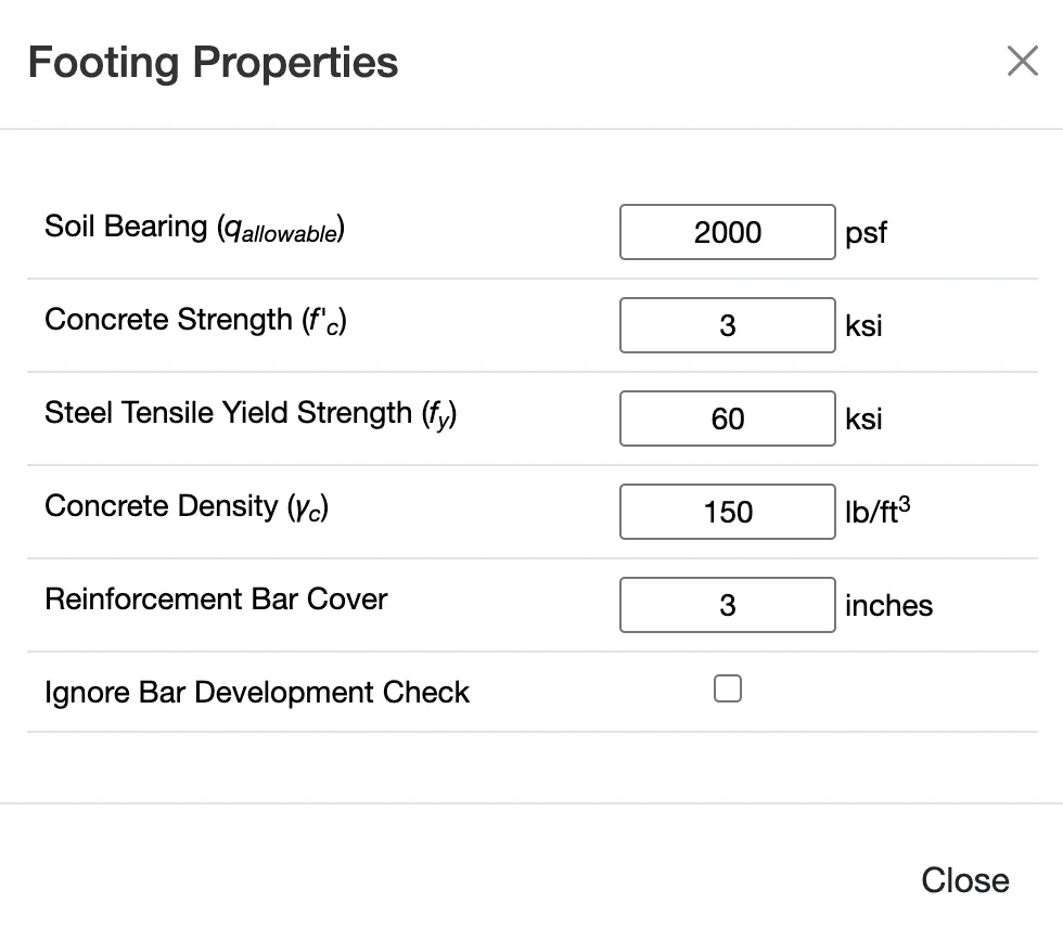
The first and most crucial step is to determine the allowable soil bearing pressure. This value is typically provided in a geotechnical report for your specific project site. It represents the maximum pressure the soil can safely support. We also need to define the concrete and steel properties for our footing design.
Soil bearing pressure has a first-order effect on footing design because it dictates how much load the ground can safely support. Soils with higher bearing capacity allow smaller footings, while weaker soils require larger footing areas to distribute loads and keep bearing pressure within allowable limits. Typical sources for allowable bearing pressures are geotechnical reports or local code tables. Always consider soil type — sand, clay, silt, or gravel — as these influence settlement and design decisions.
Concrete compressive strength and reinforcing steel yield strength are fundamental material properties that govern footing capacity. Concrete must resist compressive forces from soil pressure and flexural stresses from load moments, while reinforcing bars provide tensile resistance where concrete alone is weak. Typical design practice assumes a minimum concrete strength (often at least 3 ksi for footings) and Grade 60 reinforcing steel. Proper material specification ensures that the footing’s structural capacity matches design demands.
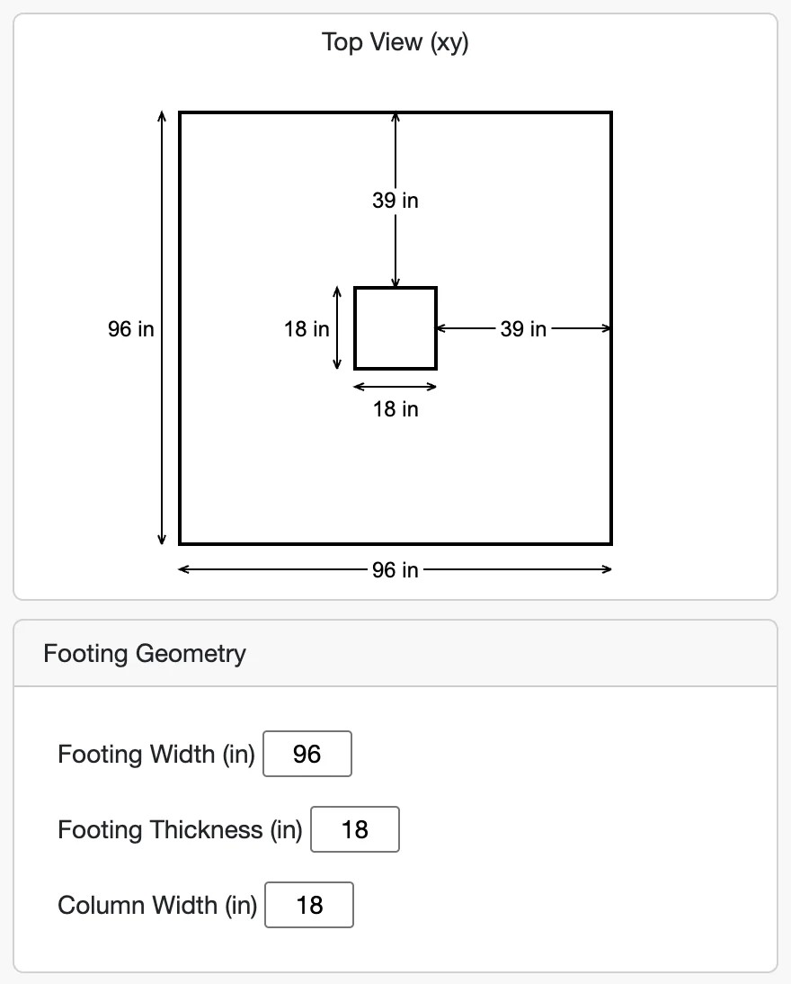
Step 2: Define Footing Geometry
The geometry of the footing — width, length, and thickness — controls how the structural load is spread into the soil and how the concrete resists bending and shear. A wider footing spreads the load over more soil area, reducing bearing pressure; a thicker footing increases capacity against one-way shear and bending. ACI 318 provisions guide minimum thickness and how to locate critical sections for shear and flexural checks.
Step 3: Apply Loads
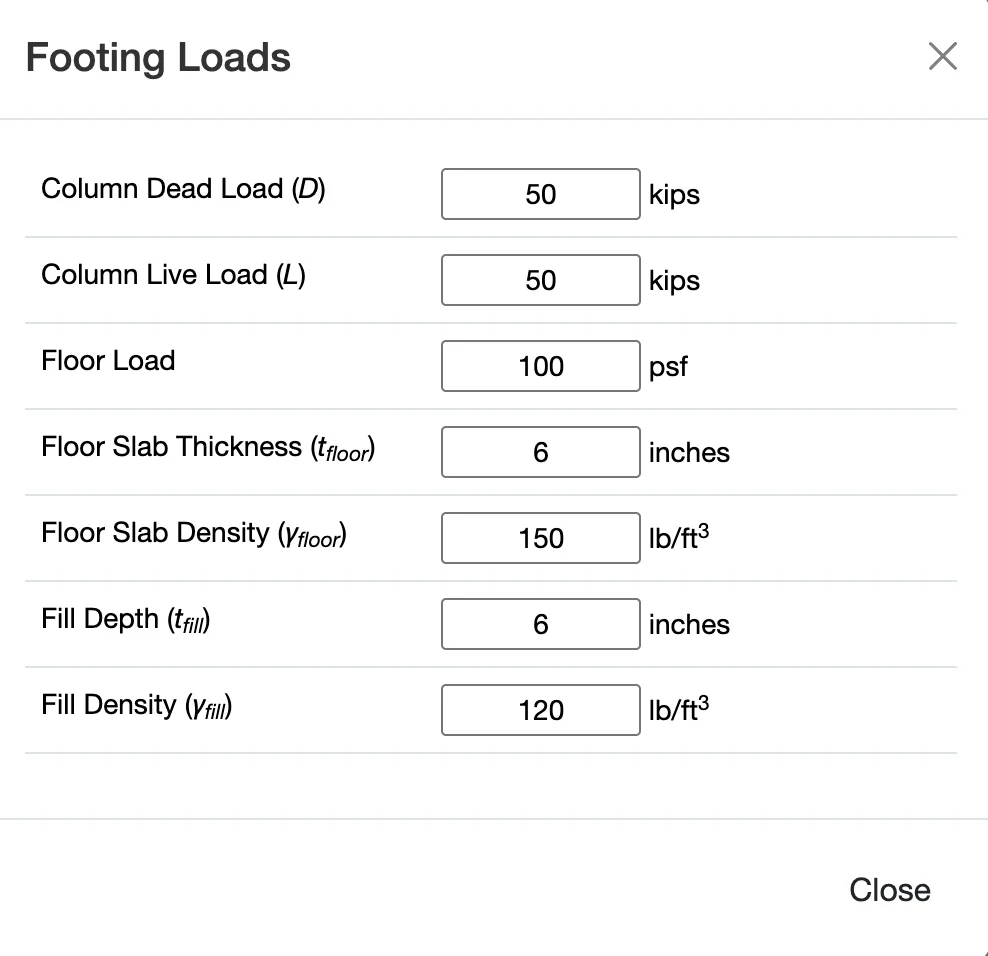
Loads are applied at the top of the column or pedestal. We need to input the service-level (unfactored) loads. The tool will then apply the appropriate load factors for the strength design checks.
For this example, we will apply a Dead Load of 50 kips and a Live Load of 40 kips.
Footing loads typically consist of vertical axial forces transmitted from columns or posts, which may include dead loads, live loads, floor slab loads, and fill weight. These loads produce downward pressure on the footing and upward reactive pressures from the soil. A critical aspect of footing design is making sure that these load combinations are factored properly for strength design, and that equivalent service loads are considered for deflection and reinforcement checks.
Step 4: Define Reinforcement
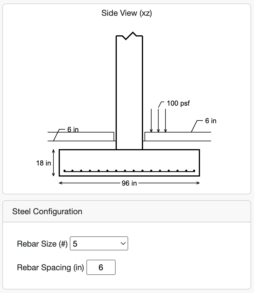
Now we specify the size of the reinforcing bars and the rebar spacing. The tool will calculate the required number of bars based on this selection.
Reinforcement in footings resists bending moments caused by soil pressure distributions and helps control cracking due to shrinkage, temperature, and load effects. Footing reinforcement is typically provided in orthogonal directions and sized based on flexural design equations. ACI 318 also specifies minimum reinforcement ratios and spacing to ensure ductile performance and to prevent brittle failure under shear and flexure.
Step 5: Review the Results
When any input is changed, WebStructural automatically calculates and displays the results. The key checks for a spread footing design are:
When reviewing design results, it's important to check each governing limit state thoroughly. Typical checks include soil bearing pressure (against allowable limits), one-way shear (critical shear across a beam section), two-way punching shear (around the loaded area), and flexural capacity for bending moments. In spread footing design, punching shear often controls around the column perimeter due to concentrated loads. Reinforcement bar development and spacing must also satisfy code requirements to ensure adequate strength and serviceability.
- Soil Bearing Pressure: Ensures the pressure exerted by the footing on the soil does not exceed the allowable limit.
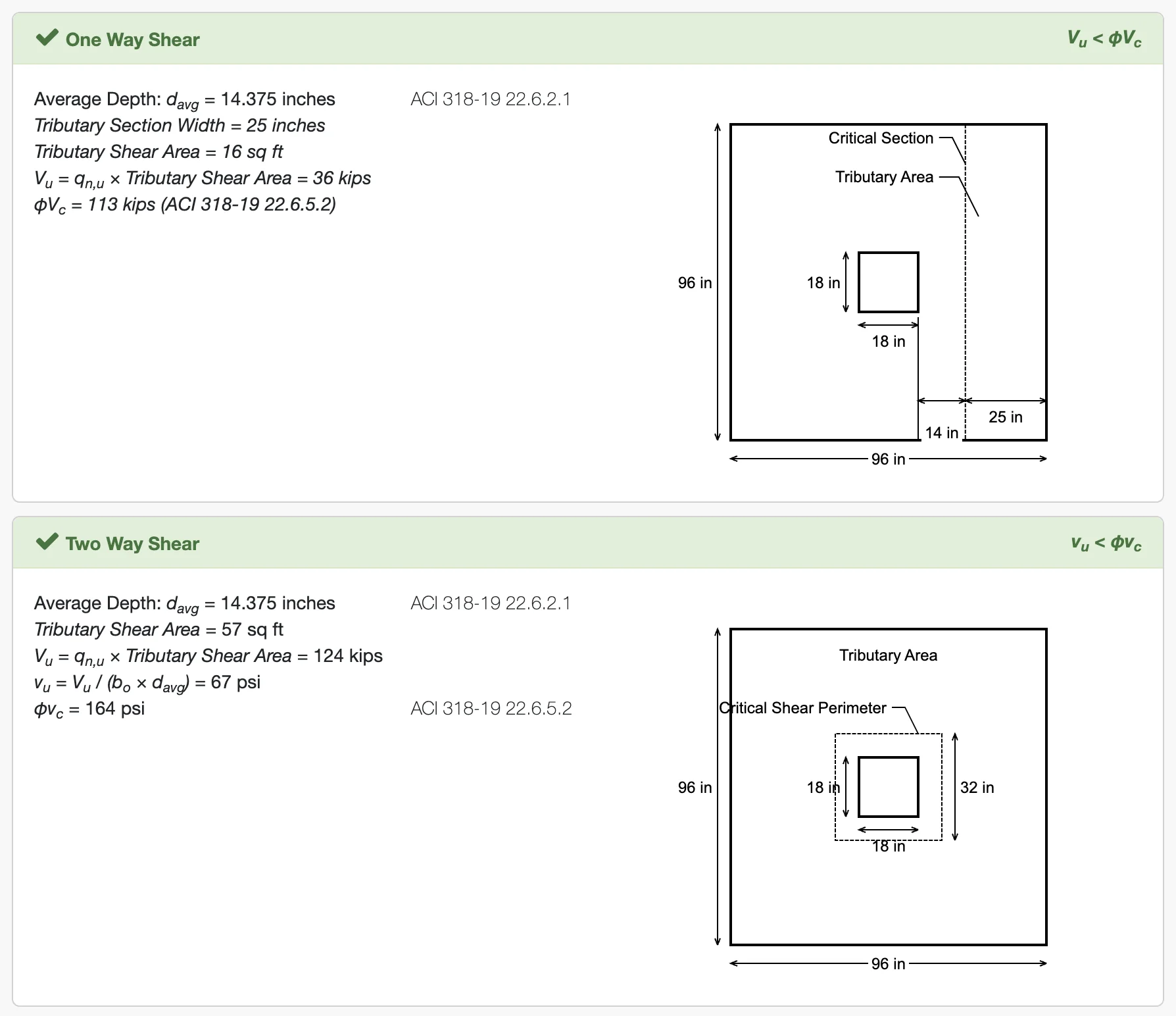
- One-Way Shear (Beam Action): Checks the shear capacity of the concrete at a critical section away from the column face.
- Two-Way Shear (Punching Shear): Checks the shear capacity of the concrete around the perimeter of the column. This is often the controlling failure mode.
- Flexure: Ensures the footing has enough reinforcing steel to resist the bending moments caused by the upward soil pressure.
- Reinforcement Bar Development: Verifies the number and size of reinforcing bars meet the design requirements.
- Bearing Load: Checks that the maximum load applied to the footing does not exceed the design capacity. The 45° dashed line represents the failure surface for this check.
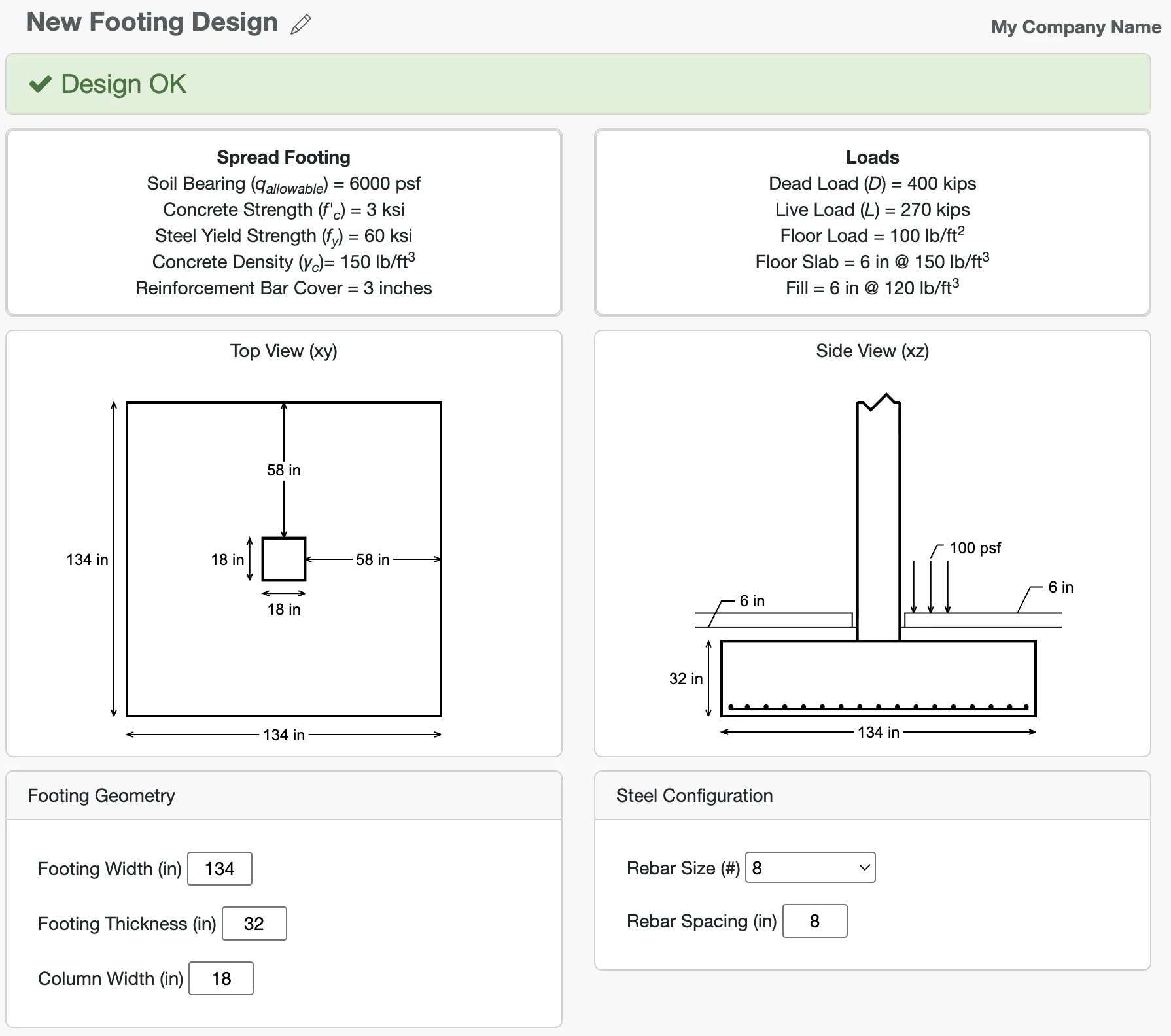
If you entered everything correctly, your design should look like this
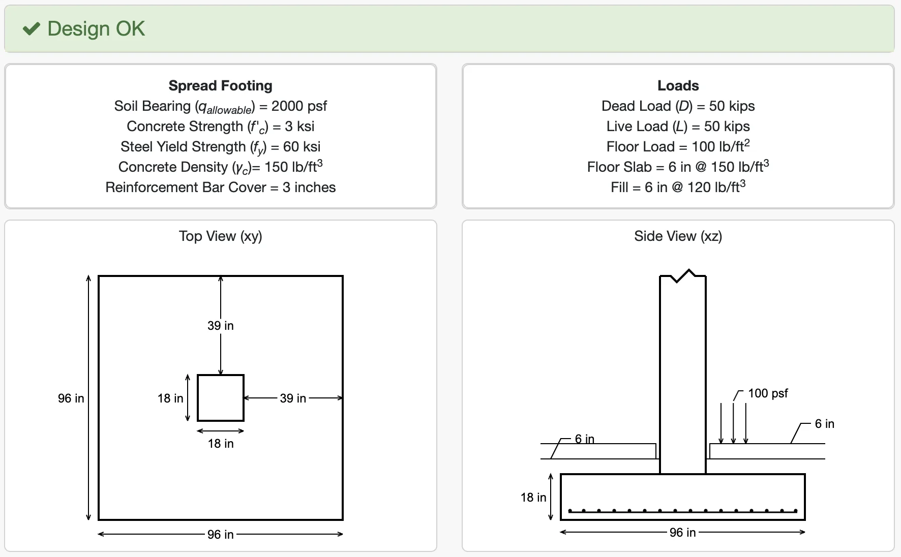
Your design report should be green.
The footing design is adequate.
The report shows that all checks pass. It also tells us we need 16 #5 bars in each direction. You can scroll down to see the detailed calculations for each check.