How to Design Anchor Bolts
Designing anchor bolts in concrete can be a complex process with many failure modes to check. However, with a systematic approach, it becomes much more manageable. Follow these steps to design most anchor bolt configurations according to ACI 318. Anchor bolt design provisions are found in Chapter 17 of ACI 318-19, which covers capacity design for cast-in anchors under tension, shear, and combined loads.
- Geometry - Define the concrete geometry and anchor layout. This includes edge distances, embedment depth, and anchor spacing.
- Materials - Select the concrete and anchor material properties.
- Loads - Apply tension and shear loads to the anchor or anchor group.
- Design Method - Choose the design code and whether to consider seismic effects.
- Review Results - Check all potential tension and shear failure modes to ensure the anchor design is adequate.
In this tutorial, we'll use the WebStructural Anchor Bolt Designer to walk through each of these steps. By the end, we'll have designed a four-bolt anchor group subject to shear and tension, checking all the required strength calculations per ACI 318-19.
Let's get started
Anchor bolt design in the United States is governed by ACI 318, specifically Chapter 17 for cast-in anchors. The code provides detailed procedures for checking each failure mode under tension, shear, and combined loading. When seismic conditions apply, additional detailing and strength requirements ensure ductile performance and prevent brittle concrete failures. The goal is to verify that every relevant limit state is satisfied for the selected load combination.
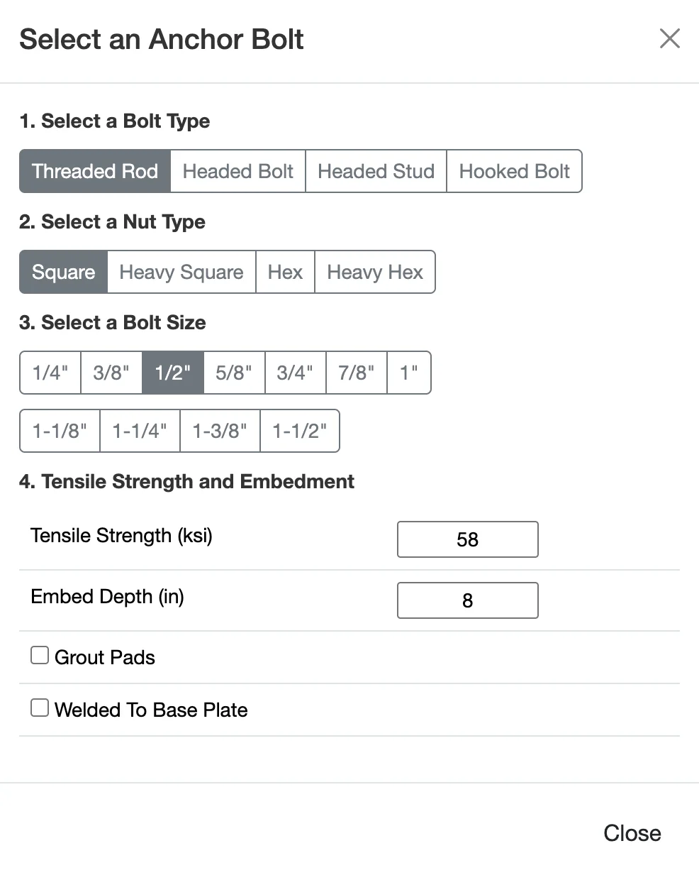
Step 1: Configure Anchor Bolt and Geometry
The first step is to configure the anchor bolt, define the geometry of the concrete slab and layout the anchors. This is critical because the capacity of the anchors is highly dependent on the distance to concrete edges and the spacing between anchors. Geometry plays a major role in anchor bolt capacity because the strength of the concrete depends on how much material is available to resist the applied load. Embedment depth increases capacity because a deeper cone of concrete must fail before the anchor can pull out. Likewise, edge distance and spacing affect capacity because closely spaced anchors or anchors near a slab edge create overlapping failure cones that reduce the concrete's ability to resist breakout.
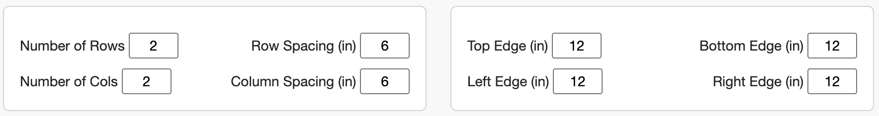
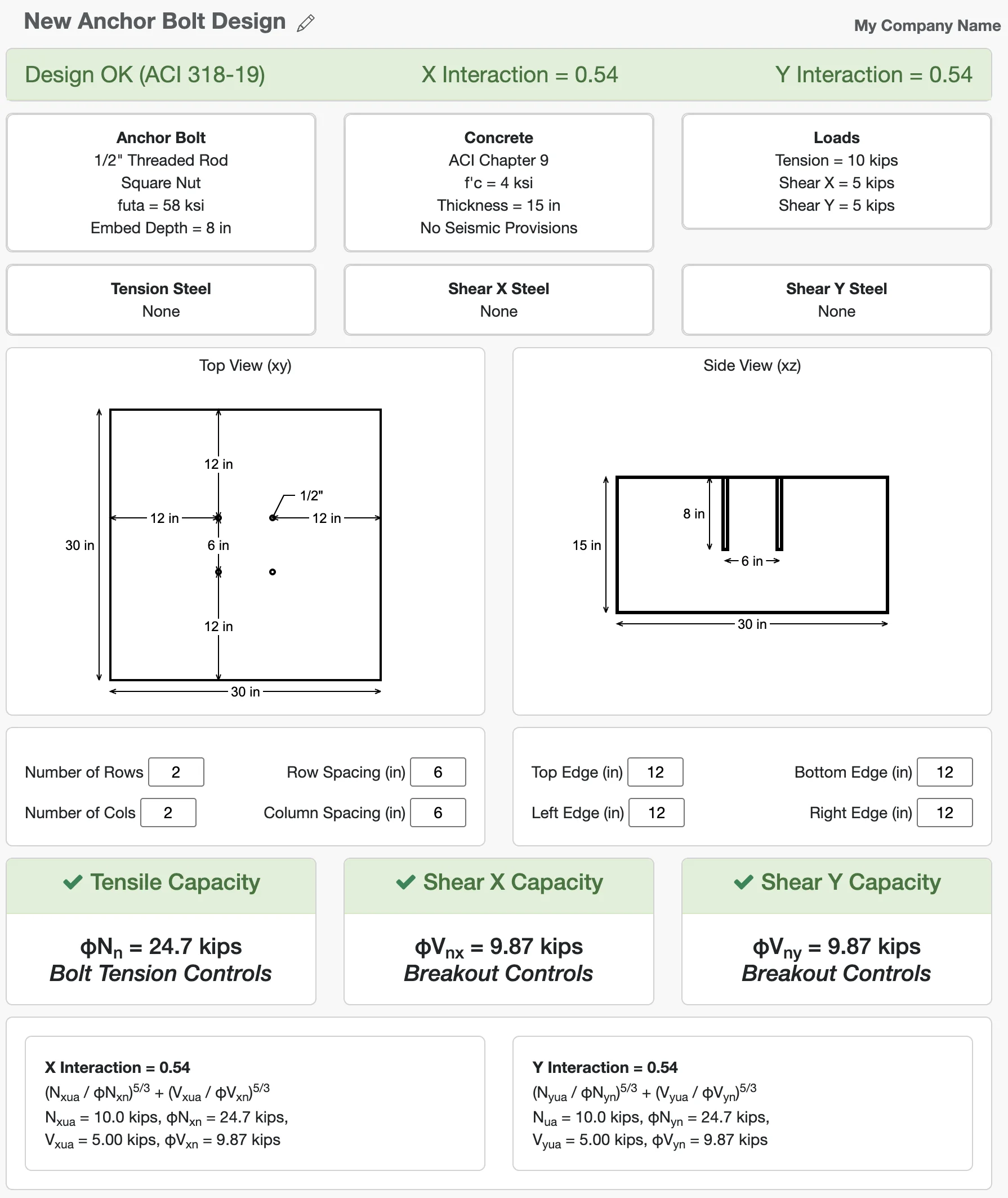
For our example, we will design a group of four anchors with 6" spacing in each direction, located 12" from two edges of a large concrete slab. Concrete edge distances and anchor spacing significantly influence the anchor capacity, so it's important to define these accurately. These values can be modified in the Geometry section of the interface, just below the drawing.
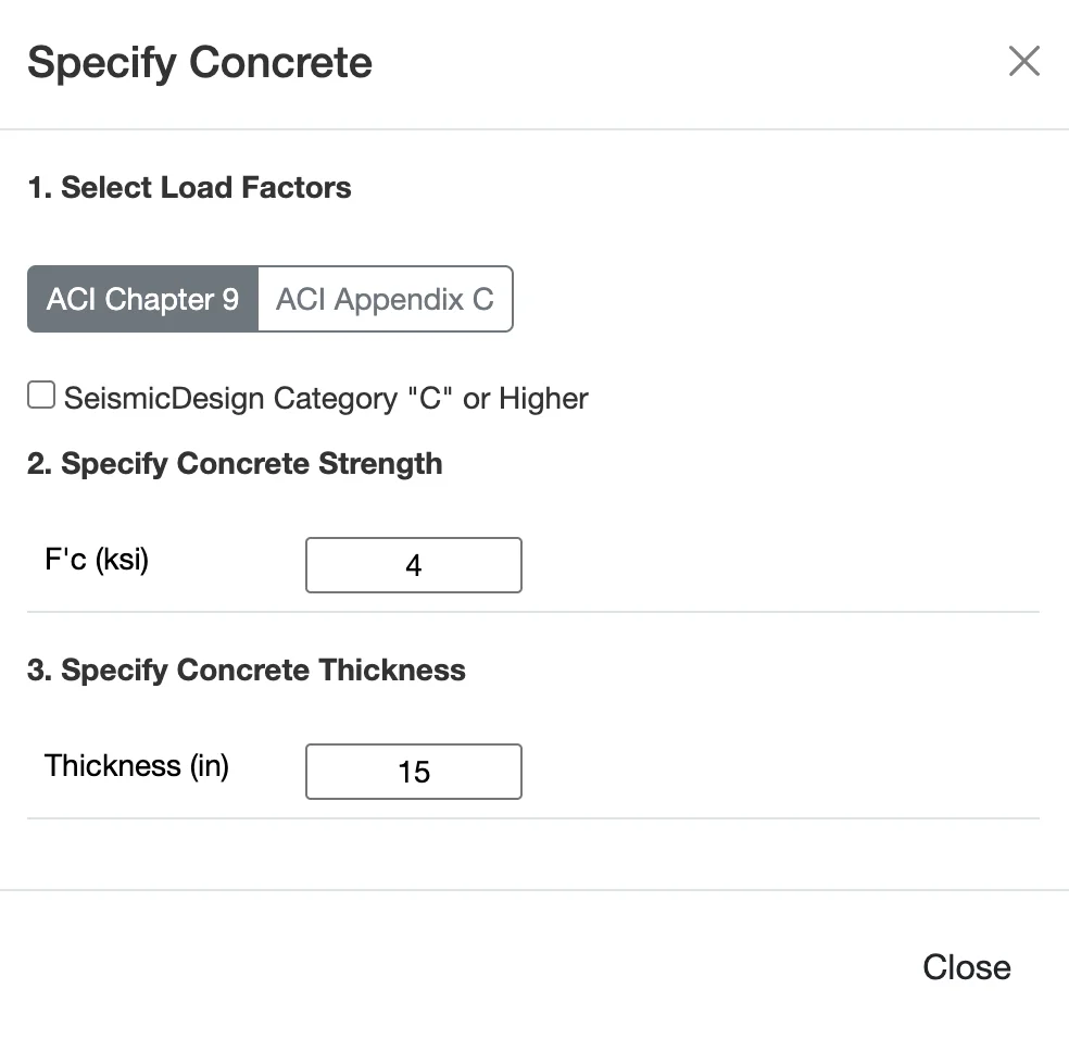
Step 2: Choose Materials
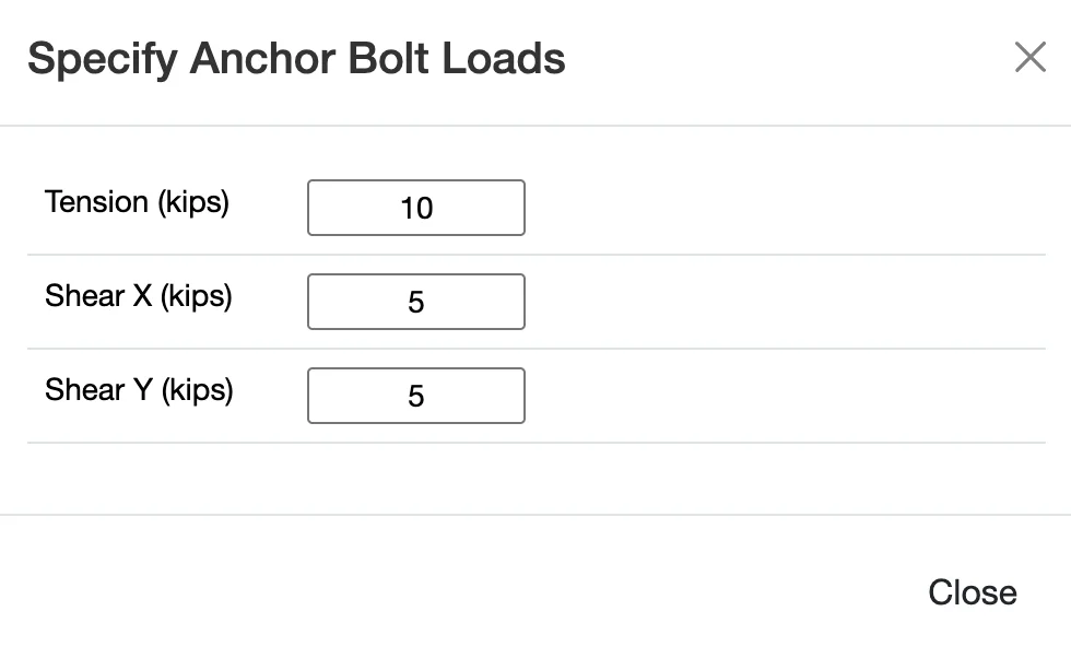
Step 3: Apply Loads
Now we need to apply loads to our anchor group. Loads are typically broken down into tension (pulling the anchor out of the concrete) and shear (pushing the anchor sideways). We will apply both. Anchor bolts are typically subjected to a combination of shear and tension. Shear loads try to slide the anchor across the face of the concrete, while tension loads try to pull it out. The controlling limit state may change depending on the direction and magnitude of the applied loading. Applying realistic load combinations is critical — underestimating loads may result in an anchor that does not perform adequately under extreme conditions.
Step 5: Review the Results
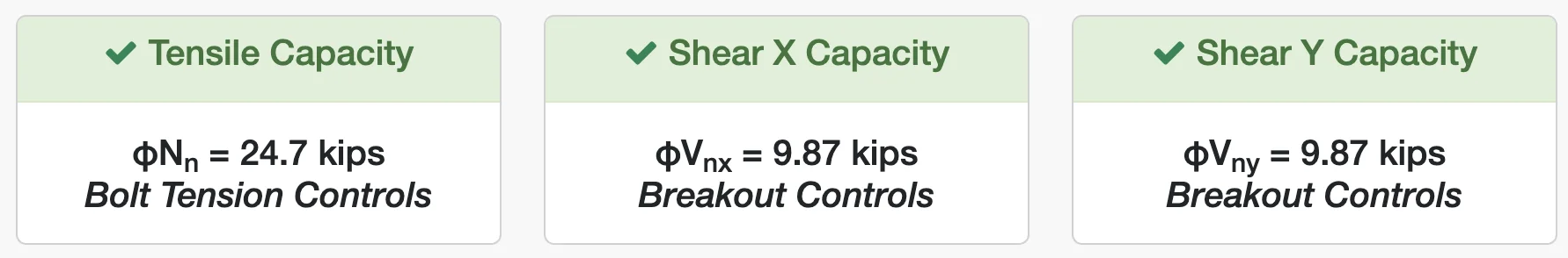
Once all the inputs are set, WebStructural automatically performs the calculations and presents the results. The results are shown as a series of capacity ratios for each potential failure mode in tension and shear. A ratio less than 1.0 means the demand is less than the capacity for that failure mode, and the check passes (indicated in green).
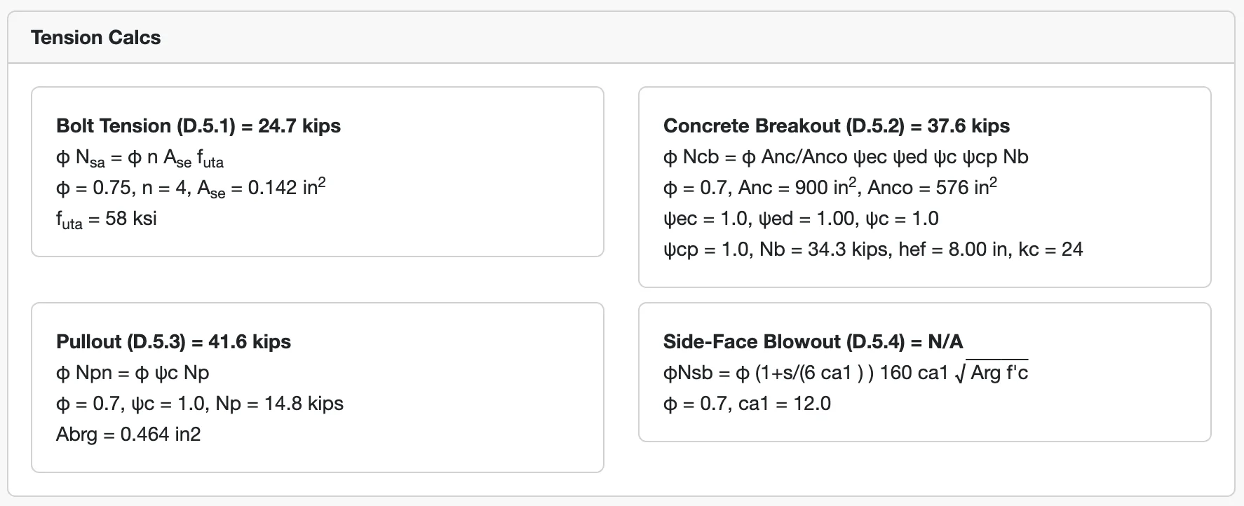
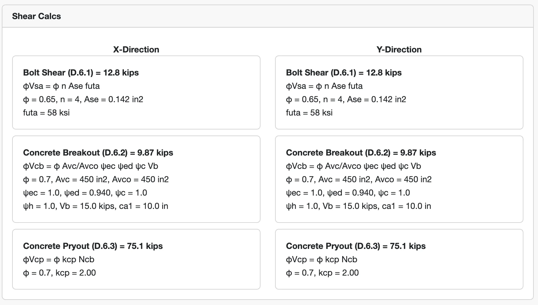
When reviewing the results, it's important to confirm that every applicable failure mode has adequate capacity. Common tension checks include anchor steel rupture, concrete breakout, pullout, and side-face blowout. Shear checks typically include steel shear, concrete breakout, and pryout. The controlling result will often depend on geometry and embedment depth. If demand exceeds capacity for any mode, adjustments such as increasing embedment, adding anchors, or changing material strength may be required.
The primary failure modes checked are:
- Tension: Steel Strength, Concrete Breakout, Pullout, and Side-Face Blowout.
- Shear: Steel Strength, Concrete Breakout, and Concrete Pryout.
Finally, an interaction check is performed for combined shear and tension.
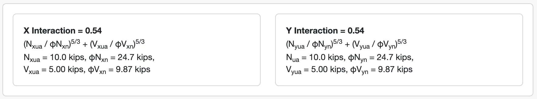
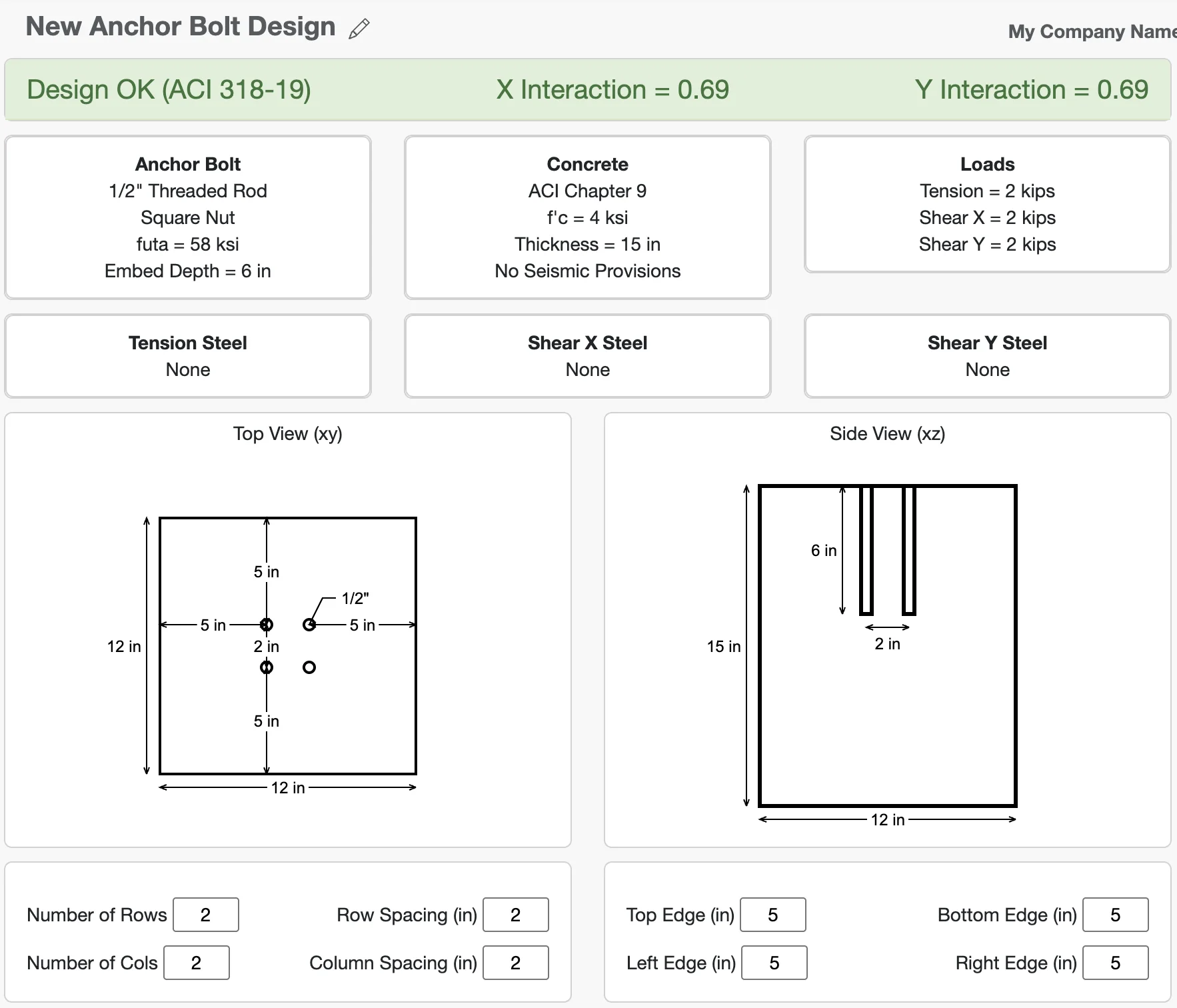
If you entered everything correctly, your design should look like this
Anchor bolt design often interacts with the design of the supported structure, such as base plates, beams, or equipment foundations. As loads or geometry change, the governing failure mode may also change. For more complex loading conditions, unusual geometries, or critical structures, consultation with a licensed structural engineer is recommended.