How to Design a Steel Beam
Designing a steel beam is simpler than it may seem. Follow these six steps to design most steel beams.
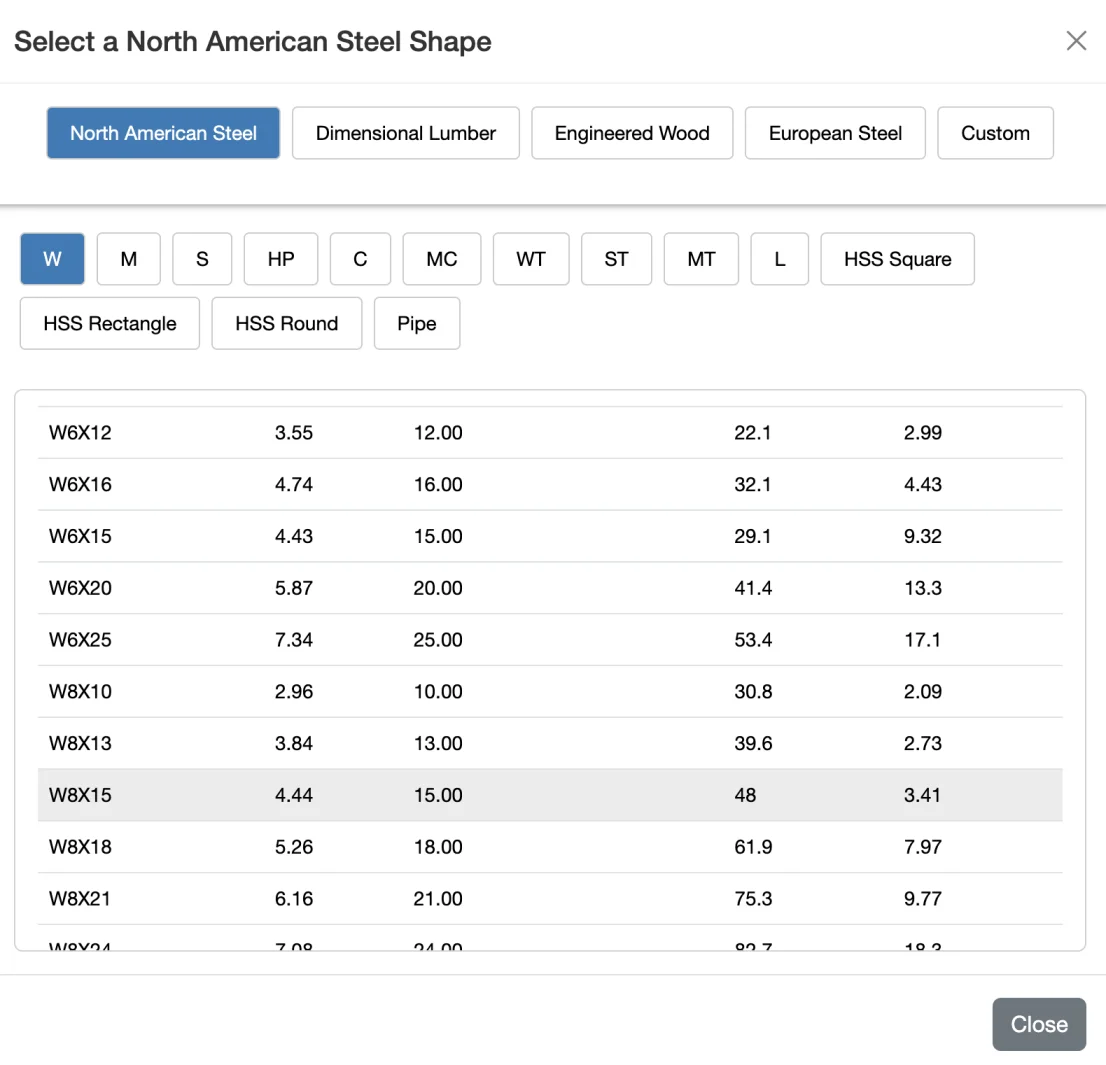
- Select a Shape - Choose the steel beam shape you want to design (for example, W-shapes / wide-flange beams).
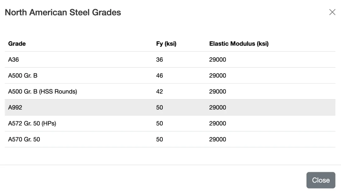
- Choose a Material Grade - Select the appropriate steel grade for your beam. A common structural steel used in the United States is ASTM A992, especially for wide-flange shapes.
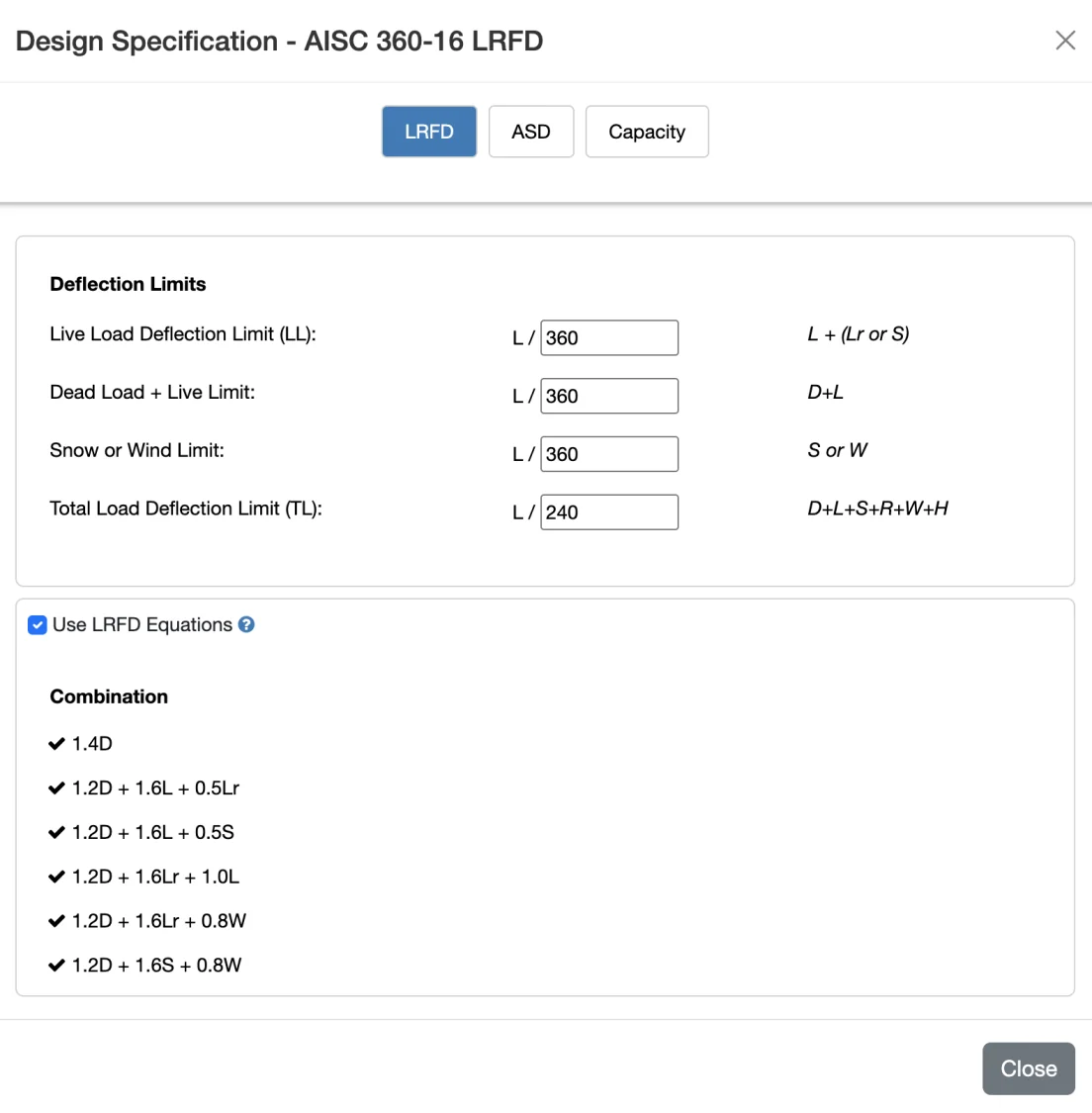
- Select a Design Method - In the United States, two common methods of beam design are ASD and LRFD. Select the method you want to use and specify deflection limits.
- Add Spans and Configure Supports - Enter the span length(s) and support conditions for your beam.
- Add Loads - Enter loads based on their type and load case (dead, live, snow, wind, etc.).
- Configure Bracing - Don't overlook bracing. Bracing has a major effect on the bending capacity of a steel beam.
In this tutorial, we'll use WebStructural to walk through each of these steps. By the end, we'll have designed a simply supported, two-span beam supporting a distributed load. WebStructural will help determine the appropriate beam size by checking bending strength, shear capacity, and deflection limits. We'll also verify resistance to lateral-torsional buckling. Because we're designing a steel beam, all capacity checks will follow the AISC 360 design specifications.
Let's get started
Step 1: Select a Shape
Let's select a W shape from WebStructural's comprehensive shape library.
This beam is roughly 8 inches deep (the first number in the shape name) and weighs 15 pounds per foot (the second number). In general, lighter beams cost less, so the most economical design is usually the lightest beam that still meets all performance requirements. After we enter the design criteria and analyze the beam, we can change the shape if the selected beam isn't adequate for the applied loads.
Step 2: Choose a Material Grade
Step 3: Select a Design Method - ASD, LRFD or Capacity
In the United States it is common to design steel with one of two methods: Load Resistance Factor Design (LRFD) or Allowable Stress Design (ASD). Both methods yield similar results.
Design Equations
If you choose ASD or LRFD, WebStructural will automatically factor your loads and apply them to the appropriate design equations. You can view these equation and exclude ones you don't want to include in analysis if you wish.
You can design a beam without load factors by unchecking the Use LRFD/ASD Equations box. This will allow you to see the capacity ratios based on service loads only. This is useful for preliminary sizing or for educational purposes. You can also choose to design a beam without any design equations at all by selecting the Capacity option. This will simply show you the capacity ratios based on the loads you enter without any load factors or design equations applied.
Deflection
Deflection is an important measure of beam performance. Beams that have excessive deflection can be strong enough to carry their design loads, but perform poorly in service. Excessive deflections can lead to user complaints including: bouncy floors, cracked building finishes, instability for mechanical equipment, etc. The International Building Code (IBC) dictates the minimum deflection for various members and load types. Deflections are typically described as a ratio or L (span) over some value to allow for comparison and standardization. For example, the deflection ratio for 0.5" deflection over a 12' beam is:
L / 288 = 12ft x 12 in/ft (span) / 0.5 in (deflection)
Now consider a beam that deflects 0.75" and is 18' long. It has an equivalent deflection ratio of L/288. In theory, these beams have the same deflection performance even though the longer span beam has a greater deflection. That is because the deflection is less noticeable over the greater distance. L/100 is often considered to be near the limit of deflection that is detectable to the human eye. L/360 is considered a minimum acceptable deflection due to live loads on floors. Keep in mind though, that is just a minimum. You can configure this setting in WebStructural for your specific use case.
Step 4: Add Spans and Configure Supports
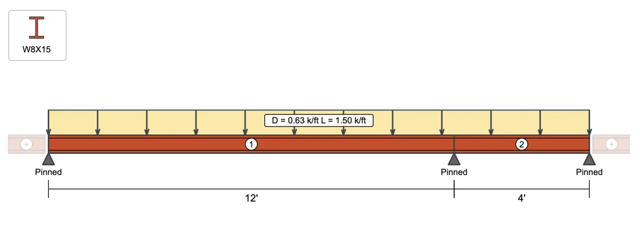
A span is the distance between points of support on a beam. A beam is often just a single span supported at both ends. However, that's not always the case. Beams can be supported anywhere along their length or they can be cantilevered beyond their end supports. To add or edit span lengths in WebStructural, simply click Spans button or click the span dimension on the drawing. You can add a span to the left or right of existing spans.
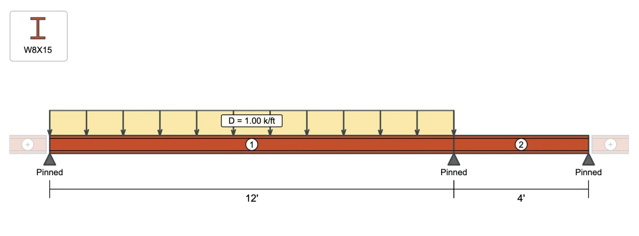
For our example we're going to add a span to the right and make it 4'-0". We'll also adjust the left-most span to 12'-0".
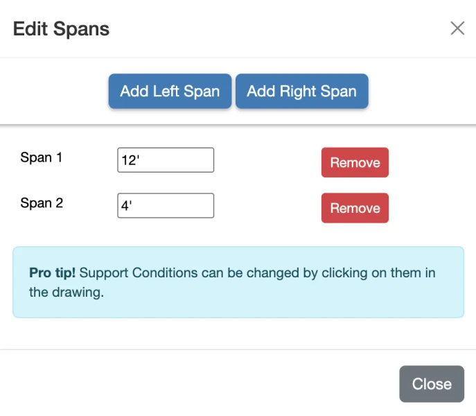
Beam support conditions can be changed in WebStructural by simply clicking on a support (the gray triangle under the beam). Clicking a support will toggle through three support types (support conditions): Pinned, Fixed, or Free.
While we could easily make either end a cantilever by simply clicking the support to change it to "Free", we'll keep everything as simply supported for this example.
Step 5: Add Loads
Load Cases
A beam can carry loads from many different sources. Below we list some of the more common types of Load Cases:
Dead loads (D) are those which are always present. Think of a concrete slab, or the weight of a wall. Those loads are always present and do not change.
Live Loads (L) are typically occupancy type loads. You are a type of Live Load in the structure you are in right now. American Society of Civil Engineers publishes a book (ASCE 7) with guidance for the amount of live load that should be used for different structures.
Roof Live Loads (Lr) are similar to Live Loads, but are specific to the roof and are typically related to construction or maintenance activities.
Snow Loads (S) are exactly want they sound like, loads cause by snow. Local building codes often dictate the appropriate ground or design snow loads to use. These are typically basic loads. Drift and unbalanced conditions should be accounted for as needed.
Other Loads are less common in beam design but can include Wind (W), Seismic or Earthquake (E), Rain (R), Lateral Earth (H), etc.
Load Types
Beams can be loaded in many ways, but most loadings that cause flexure can be described as either:
Uniform Loads These loads have units of force per unit length. With WebStructural, the default units for Uniform Loads is kips per foot (1 kip = 1000 lbs.). Uniform loads are often used to simplify repetitive and closely spaced point loads such as floor joists or roof rafters. To calculate the appropriate uniform load to apply to a beam, simply multiply the beams tributary area by the appropriate area load. Area loads and other structural loads are established by the American Society of Civil Engineers ASCE7 document and are given as pounds per square foot (psf).
Linear Loads Linear Loads are very similar to uniform loads, but rather than having a constant magnitude, vary along their length. Linear Loads also have units of force per length. Linear loads can be used to represent triangular snow drifts or beams with joists framing in at a skewed angle, or many other triangular and trapezoidal type loading.
Point Loads Point loads have units of force. The default in WebStructural is Kips (1 kip = 1000 lbs.). Point loads can be as simple as a reaction from another member such as a beam framing into another beam, or a column sitting on a beam.
Moments Moments are loads which cause rotation in the axis of a beam and have units of force times length. The default in WebStructural is kip-feet. Moments are more complex to those less familiar with them, but consider a column welded to the top of a steel beam. If a force is applied to top of the column, it will cause the beam it is attached to bend as well, just like a lever. This bending type reaction is a moment. If the force is in the direction of the beam axis (or span direction), it can be input as a moment in WebStructural. If the force applied is perpendicular to the beam axis, then a torsional moment will be introduced. WebStructural does not currently allow for torsional loads to be input.
Loading Our Beam
For our example, we'll use a dead load D = 0.63 k/ft and a live load L = 1.5 k/ft. We'll make sure to Include Self Weight too. You can edit loads by clicking any load on the drawing, clicking the Edit Loads... button above the drawing or from the main menu Edit → Loads...
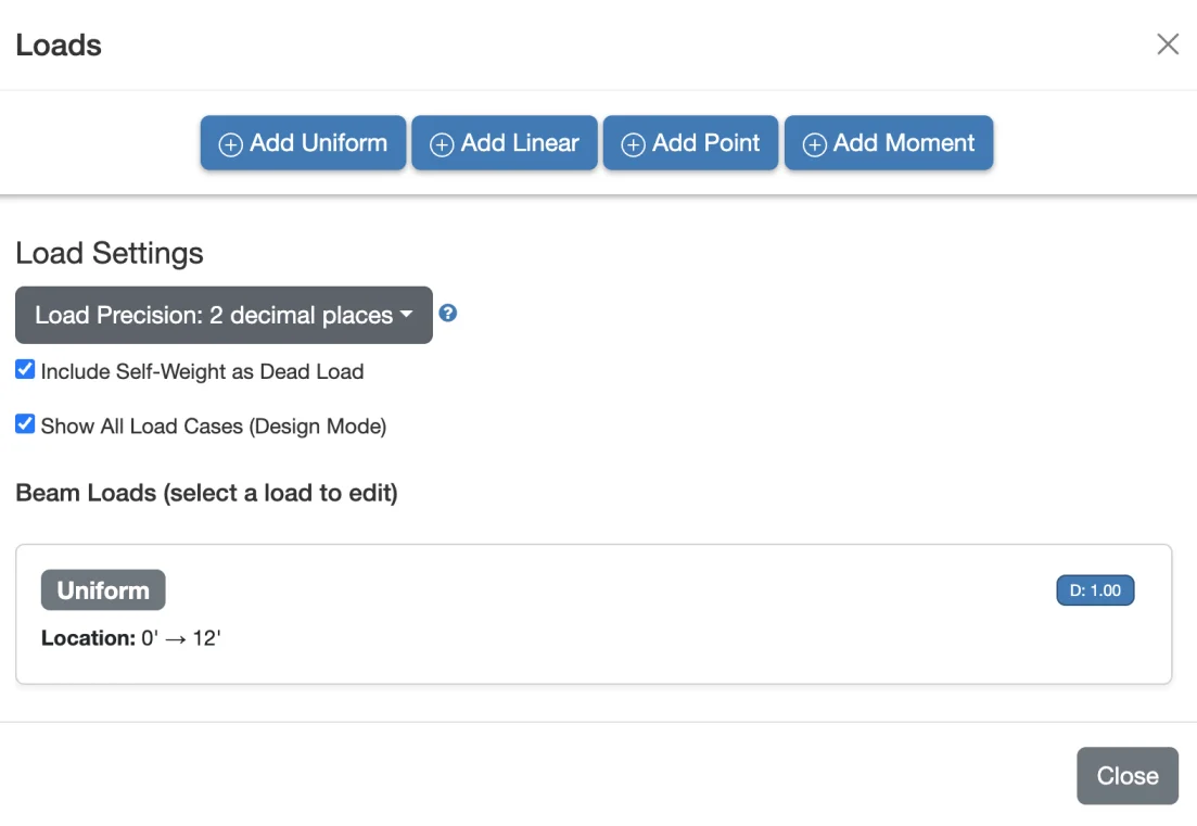
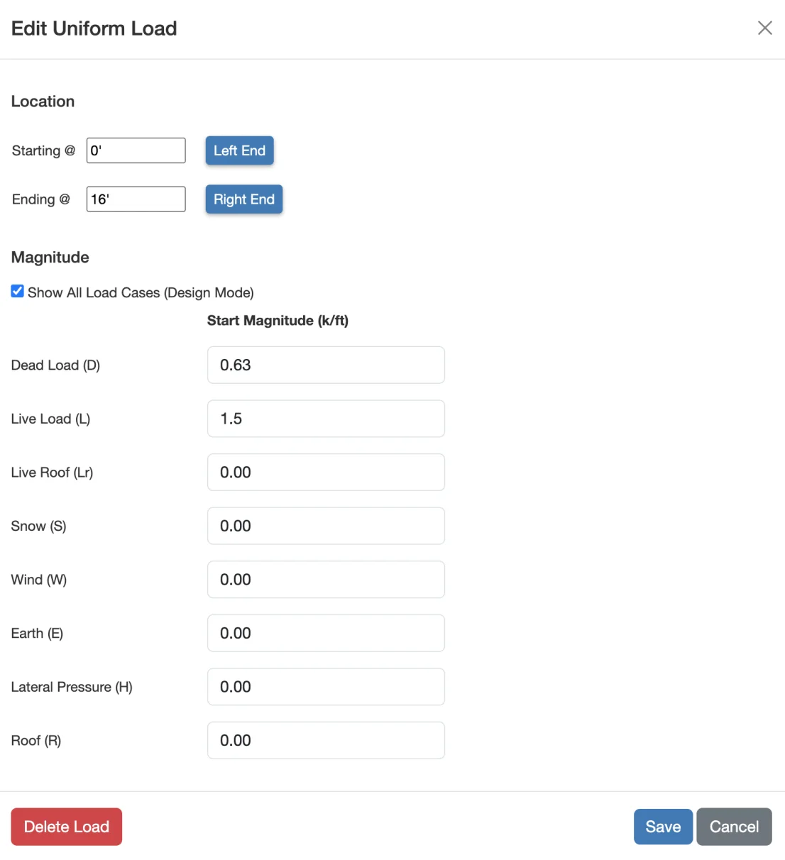
What about Load Factors? Depending on which design method you choose, (LRFD or ASD), the loads you enter will be factored for you. Simply enter the service (unfactored) loads.
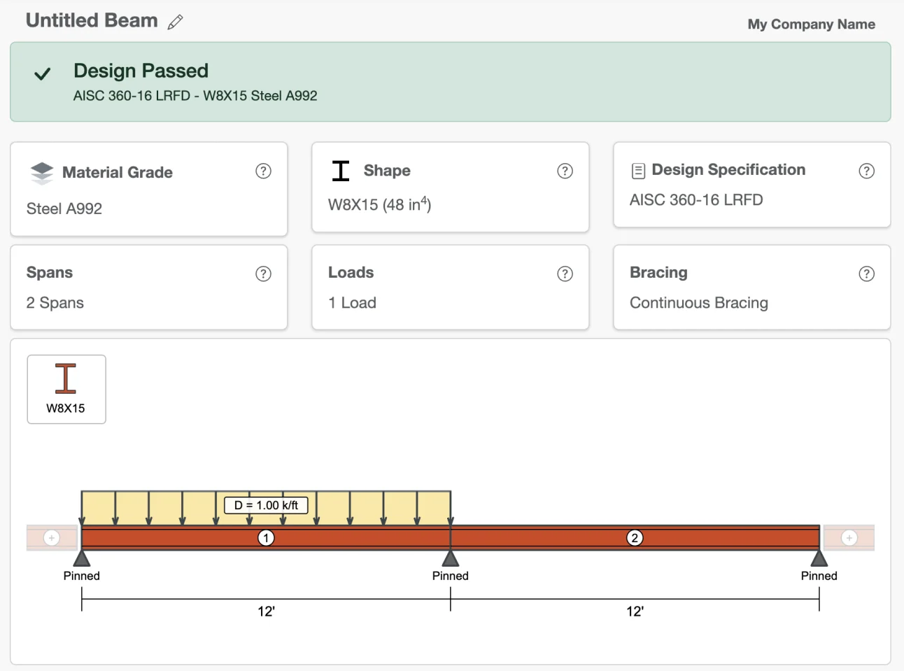
Your model should now look like this
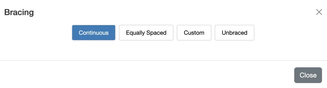
Step 6: Configure Bracing
Bracing is an incredibly important, yet often overlooked aspect of beam design. When a beam is bent, tension and compression forces are introduced. For a simple span beam (one spanning between two pinned supports), the top of the beam will be in compression. It is these compression forces that can cause a beam to buckled out-of-plane (called lateral torsional buckling or LTB). To understand this type of buckling, think of compressing a short ruler between your hands. Now think of compressing a yard stick. Which one is more likely to flex and twist when you compress it? Clearly the longer, more slender one. It is this slenderness that is directly related to buckling. If we are able to brace a beam against this type of buckling, then we can often achieve greater bending strength. WebStructural allows you to specify bracings in many different common configurations. Span supports are automatically assumed to be bracing locations. Remember, continuous bracing assumes that the compression side of the beam is braced. If you need to find the compression side of your beam just take a look at the moment diagram. The compression side will be the inside of the curve where ever you see areas of high curvature (moment). If you're unsure about bracing conditions you can always conservatively assume the beam is completely unbraced.
Finishing Touches: Design and Report
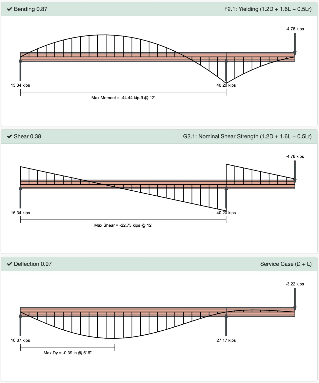
WebStructural recalculates automatically - all you need to do is review the results. This is where WebStructural shines. The app will perform a finite element analysis for the beam model. Using the design forces it calculates, it checks design capacities for the beam using the American Institute of Steel Construction (AISC 360) standards. If you happened to select an appropriate beam size (which we did), you will see a lot of green. That's good, it means the bending, shear, and deflection capacity ratios are less than 1.0. These values are a ratio of the capacity to the demand. For example, if your report reads "Bending 0.87," that means the beam configuration you selected is at 87% of its flexural capacity, according to AISC.
If your report is red, your capacity ratios are greater than 1.0 and the beam does not meet the design criteria. This means you need a bigger beam. Simply choose a different shape with a larger moment of inertia and click the Calculate button again.
If you entered everything correctly, your design should look like this
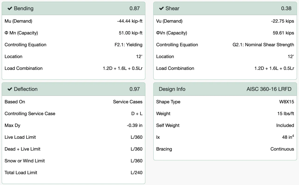
Your design report should be green.
The beam is adequately sized.
Now you can scroll down to see more details about the design, like reactions and plots of the moment, shear and deflection for each of the analyzed load cases.