Howe Truss: How It Works, With a Worked Example
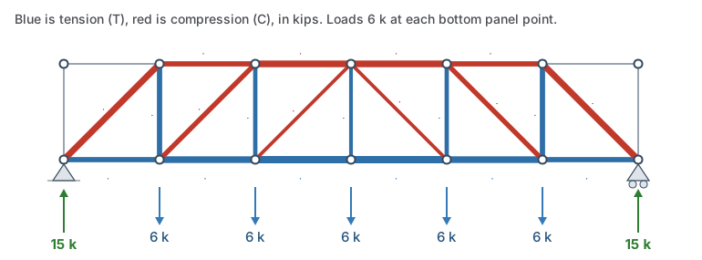
A Howe truss has parallel top and bottom chords, verticals at each panel point, and diagonals that slope up toward the middle of the span. That's the mirror of a Pratt truss, and it reverses the web forces: under gravity load the diagonals are in compression and the verticals in tension. William Howe patented it in 1840 for bridges with timber diagonals, which carry compression well, and wrought iron rods as the verticals, which carry the tension a wood joint struggles with. Many covered bridges and early railroad bridges are Howe trusses.
This tutorial works out every member force in a 36 ft Howe truss by hand, checks the critical members to the American Institute of Steel Construction (AISC) 360-22 specification, and shows why its compression diagonals need more steel than a Pratt's tension ones.
The example truss
- Span 36 ft in six 6 ft panels, 6 ft deep, so the diagonals are at 45° and 8.5 ft long.
- Pinned at the left end and on a roller at the right.
- A load at each of the five inside panel points of the bottom chord: 2 kips dead load and 4 kips live load, 6 kips in all.
- Chords are HSS4x4x1/4 and web members HSS3x3x1/4 hollow structural sections (HSS), A500 Grade C steel (yield stress Fy = 50 ksi): the same as the Pratt example, so the two compare.
The hand calculation treats every joint as a pin, so each member carries axial force alone, and leaves out the members' own weight.
Step by step
Step 1: reactions
The five loads add to 30 kips, and the truss is symmetric, so each support takes R = 15 kips.
Step 2: members that carry nothing
Look at the top corner above the left support. Only two members meet there, the end vertical and the first top chord panel, and nothing loads the joint. Two members at an angle can't balance each other, so both carry zero force. In a Howe truss these end members only frame the shape. They're often left out, which gives the truss sloped ends.
Step 3: the end diagonal, by the method of joints
At the left support the end vertical carries nothing, so the end diagonal takes the whole 15 kip reaction. At 45°:
Fdiagonal × sin 45° = 15 → Fdiagonal = 15 × √2 = 21.2 kips compression
The diagonal pushes the support joint outward with its horizontal component, 15 kips, and the first bottom chord panel holds it in with 15 kips tension.
Step 4: the chords at midspan, by the method of sections
Cut through the third panel, between 12 and 18 ft. Its diagonal runs from the bottom joint at 12 ft up to the top joint at 18 ft. Take moments about the bottom joint at 12 ft for the top chord, and about the top joint at 18 ft for the bottom chord:
M12 = 15 × 12 − 6 × 6 = 144 kip·ft → Ftop = 144 / 6 = 24 kips compression
M18 = 15 × 18 − 6 × 12 − 6 × 6 = 162 kip·ft → Fbottom = 162 / 6 = 27 kips tension
In the Pratt it's the other way round: 27 kips in the top chord and 24 in the bottom. The diagonals' direction changes which joint each chord's moment is taken about.
Step 5: diagonals and verticals, from the shear
The shear is 15, 9 and 3 kips in the first three panels, so the diagonals carry 21.2, 12.7 and 4.2 kips, all in compression. Each vertical carries the shear of the panel on its outside in tension: 15 kips next to the support, then 9 kips. The middle vertical carries 6 kips tension. It hangs the middle load from the top joint where the two middle diagonals meet.
Checking the members
These checks use allowable strength design (ASD), with the safety factor Ω = 1.67 and the full 6 kip loads (D + L). The top chord is taken as braced out of its plane at every panel point.
| Member | Force | Allowed (Pn/Ω) | Ratio |
|---|---|---|---|
| End diagonal, HSS3x3x1/4, 8.5 ft | 21.2 kips C | 39.5 kips | 0.54 |
| Vertical next to the support, HSS3x3x1/4 | 15.0 kips T | 50 × 2.44 / 1.67 = 73.1 kips | 0.21 |
| Top chord at midspan, HSS4x4x1/4, 6 ft | 24.0 kips C | 85.6 kips | 0.28 |
| Bottom chord at midspan, HSS4x4x1/4 | 27.0 kips T | 50 × 3.37 / 1.67 = 101 kips | 0.27 |
The end diagonal is the one to watch. Its buckling strength (AISC 360-22 E3):
- Slenderness: KL/r = (8.49 × 12) / 1.11 = 91.7, with K = 1 for pinned ends.
- Elastic buckling stress: Fe = π²E/(KL/r)² = π² × 29,000 / 91.7² = 34.0 ksi.
- Fy/Fe = 1.47, under 2.25, so Fcr = 0.6581.47 × 50 = 27.0 ksi.
- Allowed load: 27.0 × 2.44 / 1.67 = 39.5 kips.
In tension the same tube could carry 73.1 kips. Buckling cuts its strength almost in half, and the Howe puts its longest members in compression. That's the trade-off against the Pratt.
Run it in the frame designer
Open this Howe truss in the frame designer
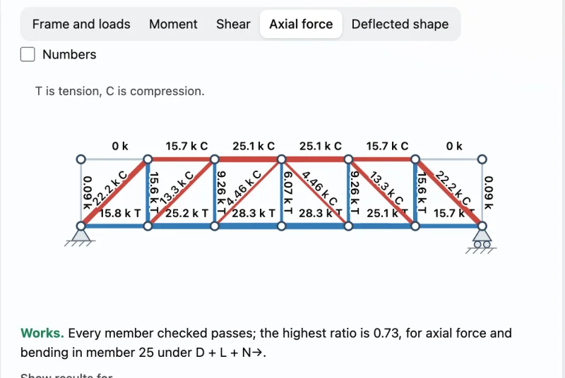
The frame designer adds the members' own weight, so its forces are a little higher: 22.2 kips in the end diagonal and 28.3 kips in the bottom chord. Its highest ratio is 0.73, in the end diagonals, against 0.54 by hand. That gap is much bigger than in the Pratt (0.38 against 0.29). Self-weight bends each diagonal a little between its ends, and in a member under compression that bending is amplified as the load approaches the buckling load (the B1 factor of AISC 360-22 appendix 8). The designer checks the amplified bending with the axial force (H1).
Change the diagonals to HSS4x4x1/4 in the designer and the highest ratio drops to 0.36, about the same as the Pratt with its smaller diagonals.
Howe, Pratt and Warren compared
The same 36 ft truss with the same sizes and loads, laid out three ways:
| Howe | Pratt | Warren | |
|---|---|---|---|
| Diagonals | Compression | Tension | Alternate |
| Verticals | Tension | Compression | None |
| End diagonal | 21.2 kips C | 21.2 kips T | 16.8 kips C |
| Largest top chord force | 24.0 kips C | 27.0 kips C | 27.0 kips C |
| Largest bottom chord force | 27.0 kips T | 24.0 kips T | 25.5 kips T |
| Highest ratio in the frame designer | 0.73 | 0.38 | 0.41 |
Frequently asked questions
Which members of a Howe truss are in compression?
Under gravity load the diagonals and the top chord are in compression, and the verticals and the bottom chord are in tension. An upward load, such as wind uplift on a roof, reverses every force, and then the Howe's diagonals are in tension.
Why use a Howe truss instead of a Pratt?
When the diagonals are good in compression and the verticals good in tension, as with timber diagonals and steel rods. Also where the main load is upward, which turns a Howe's diagonals into tension members. In an all-steel truss under gravity load, a Pratt usually needs less steel.
Is a Howe truss stronger than a Pratt truss?
Neither is stronger in general. With the same members and loads, the chord forces are about the same; what changes is which web members are in compression. In this example the Howe's long diagonals buckle first, so it's the weaker of the two.
Can I change the span or the panels?
Yes. Open the example in the frame designer and move the joints, add panels, or change the sizes and loads. It analyzes up to 50 joints.