Load Cases and Load Combinations
| D | Dead Loads |
| L | Live Loads |
| Lr | Roof Live Loads |
| S | Snow Loads |
| W | Wind Loads (strength level, as ASCE 7-10 and later give them) |
| E | Earthquake Loads |
| H | Lateral pressure due to water or dirt typically pressing on the sides of a structure |
| R | Rain Loads |
| # | Combination |
|---|---|
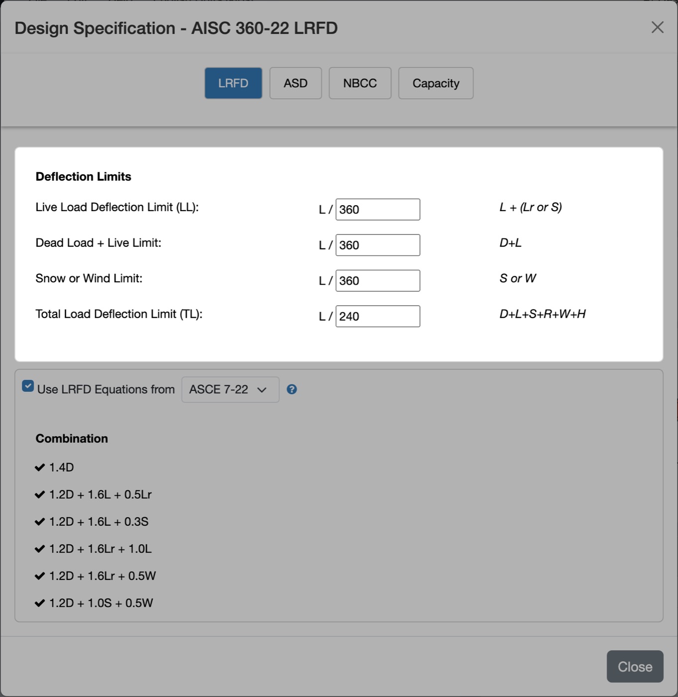
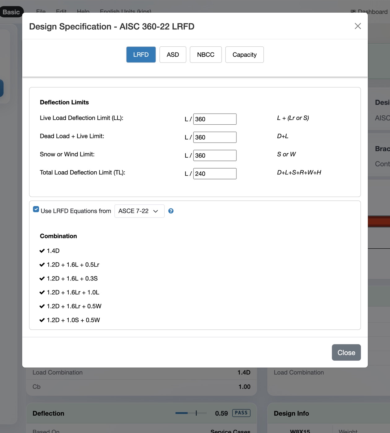
| 1 | 1.4D |
| 2 | 1.2D + 1.6L + 0.5(Lr or S or R) |
| 3 | 1.2D + 1.6(Lr or S or R) + (1.0L or 0.5W) |
| 4 | 1.2D + 1.0W + 1.0L + 0.5(Lr or S or R) |
| 5 | 1.2D + 1.0E + 1.0L + 0.2S |
| 6 | 0.9D + 1.0W |
| 7 | 0.9D + 1.0E |
| # | Combination |
|---|---|
| 1 | D |
| 2 | D + L |
| 3 | D + (Lr or S or R) |
| 4 | D + 0.75L + 0.75(Lr or S or R) |
| 5 | D + 0.6W or D + 0.7E |
| 6 | D + 0.75L + 0.75(0.6W) + 0.75(Lr or S or R) |
| 7 | D + 0.75L + 0.75(0.7E) + 0.75S |
| 8 | 0.6D + 0.6W |
| 9 | 0.6D + 0.7E |
Wind loads have been strength-level loads since ASCE 7-10, so they take 1.0W in LRFD and 0.6W in ASD. Older editions used service-level wind with 1.6W and 1.0W. Wind and earthquake loads can act either way, so the Beam Designer also checks uplift, with the load reversed: 0.9D − 1.0W in LRFD, for example.
Which combination usually governs
Every combination has to be checked, but a few usually decide the size of a member:
- Floor beams and joists: 1.2D + 1.6L in LRFD, and D + L in ASD.
- Roofs with snow: 1.2D + 1.6S + 0.5W in LRFD, and D + S in ASD. Where the roof live load is larger than the snow load, Lr takes the place of S.
- Light roofs in high wind: 0.9D − 1.0W in LRFD, and 0.6D − 0.6W in ASD. The member lifts, so its bottom flange needs bracing, and the connections, posts and anchors must hold it down.
- Mostly dead load: 1.4D governs in LRFD when the live load is less than an eighth of the dead load, such as a beam carrying a masonry wall.
- Braces, shear walls and frames: the wind and earthquake combinations, 1.2D + 1.0W + L and 1.2D + 1.0E + L, along with their 0.9D uplift partners.
Worked example: a roof beam
A steel roof beam spans 20 ft, with beams 8 ft apart. Each roof load in pounds per square foot (psf), times the 8 ft of roof the beam carries, gives its load along the beam in pounds per foot (lb/ft). There is no floor live load, rain or earthquake load.
| Load | psf | lb/ft |
|---|---|---|
| D, roof deck, insulation and beam | 15 | 120 |
| Lr, roof live load | 20 | 160 |
| S, snow | 25 | 200 |
| W, wind pushing down | 10 | 80 |
| W, wind lifting up | 25 | 200 |
In the LRFD combinations, snow is the largest of Lr, S and R, so it is the one used wherever the combination says "Lr or S or R":
| # | Combination | Worked out | lb/ft |
|---|---|---|---|
| 1 | 1.4D | 1.4(120) | 168 |
| 2 | 1.2D + 1.6L + 0.5S | 1.2(120) + 0.5(200) | 244 |
| 3 | 1.2D + 1.6S + 0.5W | 1.2(120) + 1.6(200) + 0.5(80) | 504 |
| 4 | 1.2D + 1.0W + L + 0.5S | 1.2(120) + 1.0(80) + 0.5(200) | 324 |
| 5 | 1.2D + 1.0E + L + 0.2S | 1.2(120) + 0.2(200) | 184 |
| 6 | 0.9D − 1.0W | 0.9(120) − 1.0(200) | −92 |
| 7 | 0.9D + 1.0E | 0.9(120) | 108 |
Combination 3 governs, at 504 lb/ft. The moment at midspan is wL²/8 = 504 × 20² / 8 = 25,200 lb-ft, or 25.2 kip-ft. Combination 6 lifts the beam with a net 92 lb/ft, so its bottom flange is in compression and needs bracing, and its connections must hold it down.
In ASD, D + S governs at 120 + 200 = 320 lb/ft, a moment of 16.0 kip-ft, and 0.6D − 0.6W gives a net uplift of 72 − 120 = 48 lb/ft.
The two methods land on nearly the same beam. For steel bending, φ is 0.9 and Ω is 1.67, so the beam needs a nominal moment Mn of 25.2 / 0.9 = 28.0 kip-ft in LRFD and 16.0 × 1.67 = 26.7 kip-ft in ASD. LRFD asks for about 5% more here because most of the load is snow, which it treats as less certain than dead load.
Load combinations calculator
Enter your loads to see every ASCE 7-22 or 7-16 combination and which one governs. Use one unit for all of them: psf, lb/ft or kips. Wind and earthquake loads act both ways, so enter them as positive numbers. The values below are the roof beam above.
Wind is strength level, as ASCE 7-10 and later give it. Lateral soil and water pressure (H) is left out. To size the member as well, the Beam Designer applies these same combinations.
What changed in ASCE 7-22
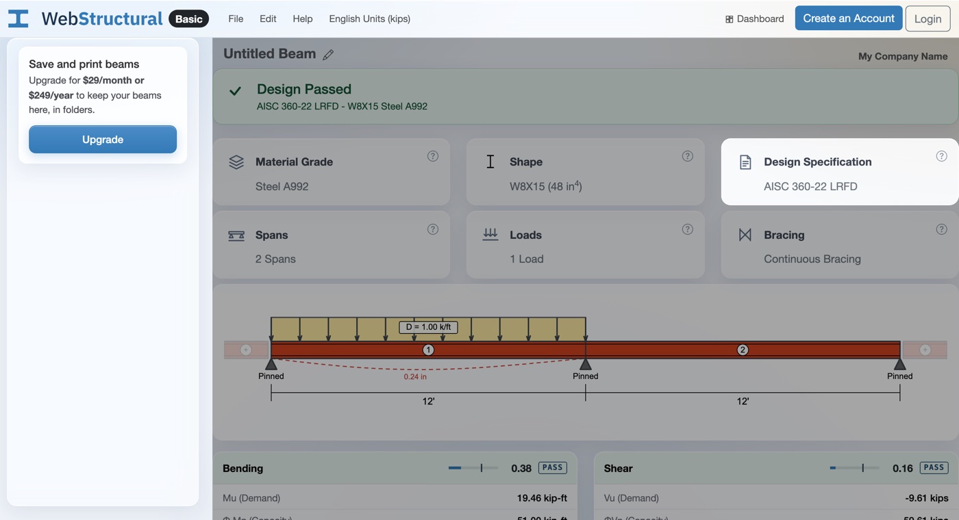
ASCE 7-22, which the 2024 International Building Code adopts, maps ground snow loads at strength level, the way ASCE 7-10 did for wind. Its snow loads are larger, and the factor on snow in the snow-led combination drops from 1.6 to 1.0 in LRFD, and from 1.0 to 0.7 in ASD (D + 0.7S). The snow factors in the other combinations change to match, so use ASCE 7-22's own tables on a project built to it. Putting a 7-22 snow load into the 7-16 combinations above overstates snow by about 60%. The calculator on this page, and the beam, column and frame designers, let you pick ASCE 7-22 or 7-16; new designs start on 7-22, and designs saved before October 15, 2026 stay on 7-16.
Load combination questions
What is the difference between a load case and a load combination?
A load case is one kind of load on its own, such as dead, live, snow or wind. A load combination adds the load cases together with factors, such as 1.2D + 1.6L, for the loads likely to act at the same time.
Why is wind 0.6W in ASD and 1.0W in LRFD?
Since ASCE 7-10, wind maps give strength-level wind loads, so LRFD uses them as they are, with a factor of 1.0. ASD multiplies them by 0.6 to bring them back to the service level that allowable stresses were set for.
What does 0.9D mean in a load combination?
In uplift and overturning, dead load helps hold the structure down. Using 0.9D in LRFD, or 0.6D in ASD, assumes there is less dead load than estimated, which is on the safe side.
Can I mix LRFD and ASD?
Not for one member. Use LRFD loads with LRFD capacities (with the resistance factor), or ASD loads with ASD capacities (with the factor of safety or allowable stresses). Steel can be designed either way; wood is usually designed in ASD.
Do I have to check every load combination?
Yes, but combinations with loads you don't have drop out, and a few usually govern: 1.2D + 1.6L for floors, 1.2D + 1.6S for snowy roofs and 0.9D − 1.0W for light roofs in wind. The calculator on this page checks them all.